
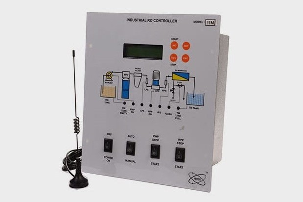


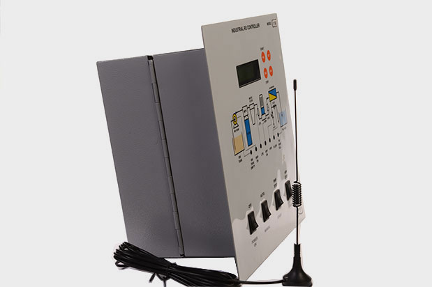

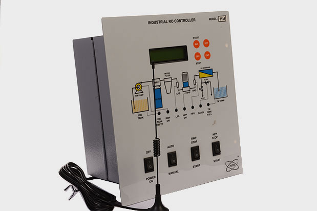
Automation Philosophy:
The Industrial RO control panel provides for very convenient mounting and easy field cable terminations. Removable terminals blocks are provided for easy terminations. Different sizes of terminals are selected for process and power connections to avoid wrong connections. The industrial RO control panel is based on state of the art technology processor. It has 6 digital inputs and four outputs. It also has Conductivity and Flow (pulse type) Sensor inputs. It can be set for Manual pre-treatment operation or Automatic pre-treatment operation. On powering the controller it checks for Raw Water Tank (RWT) level and the Treated Water Tank (TWT) level. On receiving signals that the RWT is not empty and TWT is not full, it starts up the Raw water Pump (RWP). A Low Pressure Switch (LPS) check the pressure developed at the suction of HPP. On receiving the signal that pressure is developed (LPS) at the suction of High Pressure Pump (HPP), it opens the Flush (reject) Solenoid valve for a settable time, ensuring slow flush. After this, the HPP is started for a settable time ensuring fast flush. At the end of this time Flush Solenoid valve is closed and RO is started/operational. The controller continuously checks the pressure (LPS) at the HPP suction. Should it fall, a message is displayed with an LED indication on the front panel. After a settable delay if this condition prevails, the RO is shut with a message on the LCD screen. The system can be restarted only with activation of the Start key or Power reset. If during RO in operation; - RWT empty signal is received, both the pumps stop immediately with a message on the LCD, and an LED indication for RWP level. RO can be restarted on activating Start key or Power reset. - TWT full signal is received, a flush sequence is carried out and then both the pumps stop with a message on the LCD screen and an LED indication. Once TWT full signal goes off, Slow and Fast flush sequence is initiated and RO starts. - High Pressure switch (HPS) activation is received, both the pumps stop immediately with a message on the LCD, and an LED indication for HPS. RO can be restarted on activating Start key or Power reset. - Conductivity value exceeds set High level, a message is displayed till the time value is between High and Very High Limits set. If the Conductivity value exceeds the Very High limit set, both the pumps stop immediately with a message on the LCD. RO can be restarted on activating Start key or Power reset. - Any electrical faults at RWP and / or HPP such as Overload, Dry Run, Over Voltage, Under Voltage the RO stops after the set trip values and delays, with relevant fault display on the LCD. Conductivity value, Voltage, Pump Current and various states are displayed on the LCD screen.
Manual Mode: - RWP and HPP can be started through from panel keys. HPP is interlocked with RWP in this mode. The pump motor protection is active in this as well.
- Input voltage: 230VAC, 50Hz
- Output current:10 A.
- Resolution:Current: - 0.1 A
- Environmental: 1. Working Temp : 0 to 55° C 2. Storage Temp : 10 to 70° C 3. Relative humidity : 0 – 95 % Non-Condensing 4. Warm up time : 10 Sec
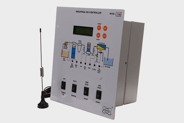
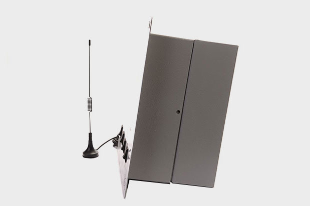
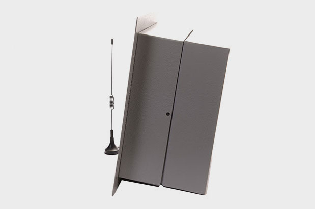
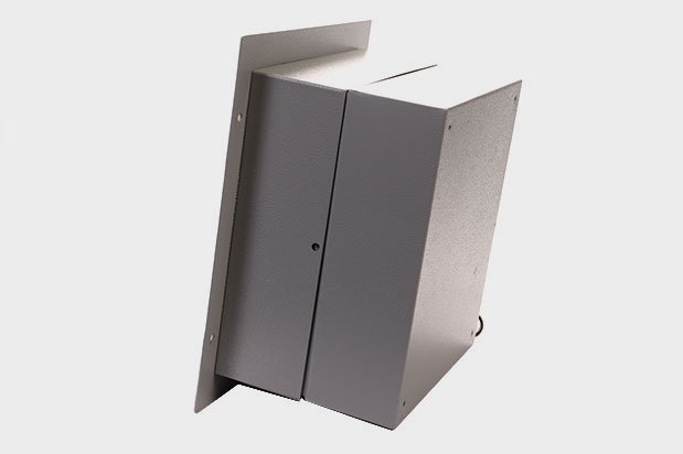
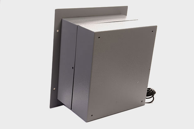
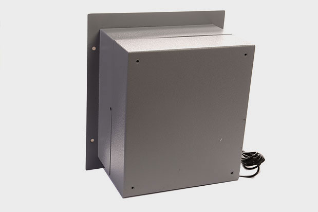
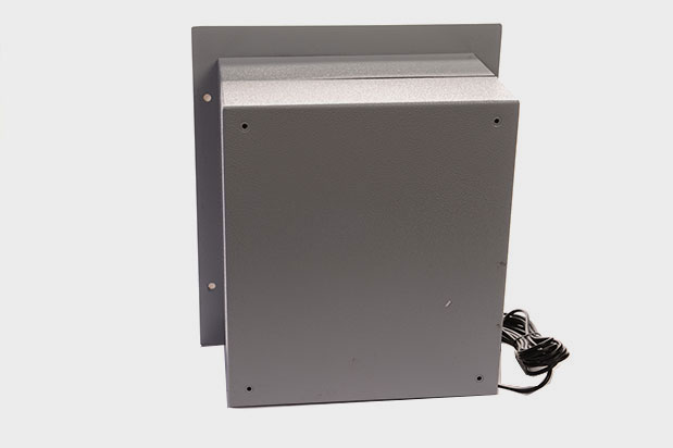
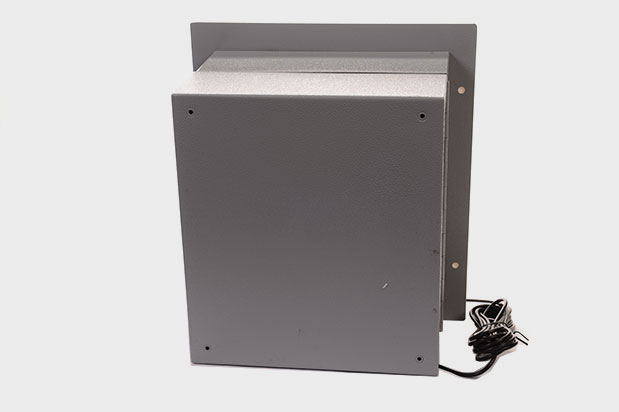
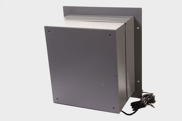
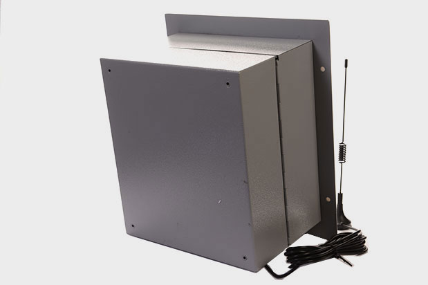
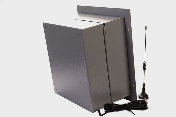
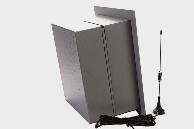
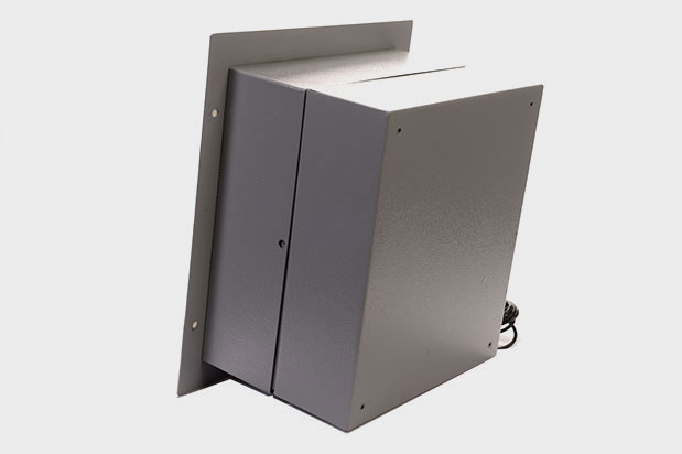
- Enclosure:
1. Mounting : Panel mounting.
2. Dimensions : 165 (W) X 60 (L) X 115 (H).
Cutout 157 (W) x 109 (H).
All dimensions are in mm. - Field Calibration: Current Calibration (Offset) can be done at site
- Cutout Dimensions: Current Calibration (Offset) can be done at site
- Field Calibration: Current Calibration (Offset) can be done at site
- Field Calibration: Current Calibration (Offset) can be done at site
- 16 x 2 LCD display
- User Programmable.
- Set Parameter password protected.
- 4 key interface for onsite programming.
- Message Display for on-going process.
- Message Display for faults.
- Front LED indication for status.
- Direct display RUN-HOUR.
- Direct display Total cumulative flow.
- WORKING:
There are two mode of operation,
1) Auto Mode.
2) Manual Mode.
All the protections like Overload, current unbalance are activated in Auto as well as manual mode. Auto/ Manual selection is done from front switch. In any mode, if the faults are present controller immediately turns off the motor having the fault.
In Auto mode controller sense digital inputs & as per digital inputs it controls the process. The digital inputs are as follows,
1) Auxillary I/P 1(Raw Water Empty) :- Normally it should be OPEN.
2) Auxillary I/P 2(Doser)- : - Normally it should be OPEN or SHORT as per dosing pump requirement.
3) Treated water Full Level(TWL)- :- Normally it should be SHORT.
4) High Pressure (HP)- :- Normally it should be OPEN.
5) Low Pressure (LP)- :- Normally it should be SHORT.
6) Conductivity Input-- :- It is a input from conductivity sensor.
7) Flow input – :- It is a input from Flow sensor.
In manual mode there are two separate switches, one for each motor to turn ON and OFF. In manual mode the motor operation is independent from digital inputs, but there is the protection of electrical un-healthy conditions.
LED Indications:
There are seven LEDs at front panel, for motor status, fault status & Fault Alarm status.
Front Switches:
1. Power supply ON/OFF switch.
2. Auto / Manual selection switch.
3. RWP (Motor1) manual ON/OFF control
4. HPP(Motor 2) manual ON/OFF control